- 您现在的位置:买卖IC网 > Sheet目录335 > ISL97635IRZ (Intersil)IC LED DRVR WHT/RGB BCKLGT 24QFN
�� �
�
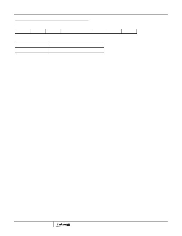
�ISL97635�
�REGISTER� 0x09�
�OUTPUT� CHANNEL� REGISTER�
�CH7�
�Bit� 7� (R/W)�
�CH6�
�Bit� 6� (R/W)�
�CH5�
�Bit� 5� (R/W)�
�CH4�
�Bit� 4� (R/W)�
�CH3�
�Bit� 3� (R/W)�
�CH2�
�Bit� 2� (R/W)�
�CH1�
�Bit� 1� (R/W)�
�CH0�
�Bit� 0� (R/W)�
�BIT� ASSIGNMENT�
�CH[7..0]�
�BIT� FIELD� DEFINITIONS�
�CH7� =� Channel� 7,� CH6� =� Channel� 6� and� so� on�
�FIGURE� 29.� OUTPUT� CHANNEL� REGISTER�
�Components� Selections�
�According� to� the� inductor� Voltage-Second� Balance� principle,�
�the� change� of� inductor� current� during� the� switching� regulator�
�On-time� is� equal� to� the� change� of� inductor� current� during� the�
�switching� regulator� Off-time.� Since� the� voltage� across� an�
�inductor� is� as� shown� in� Equation� 16:�
�Inductor�
�The� selection� of� the� inductor� should� be� based� on� its�
�maximum� current� (I� SAT� )� characteristics,� power� dissipation�
�(DCR),� EMI� susceptibility� (shielded� vs� unshielded),� and� size.�
�Inductor� type� and� value� influence� many� key� parameters,�
�including� ripple� current,� current� limit,� efficiency,� transient�
�V� L� =� L� ×� Δ� I� L� ?� Δ� t�
�and� Δ� I� L� @� On� =� Δ� I� L� @� Off,� therefore:�
�(� V� I� –� 0� )� ?� L� ×� D� ×� t� S� =� (� V� O� –� V� D� –� V� I� )� ?� L� ×� (� 1� –� D� )� ×� t� S�
�(EQ.� 16)�
�(EQ.� 17)�
�performance� and� stability.�
�The� inductor� ’s� maximum� current� capability� must� be�
�adequate� enough� to� handle� the� peak� current� at� the� worst�
�case� condition.� If� an� inductor� core� is� chosen� with� too� low� a�
�current� rating,� saturation� in� the� core� will� cause� the� effective�
�where� D� is� the� switching� duty� cycle� defined� by� the� turn-on�
�time� over� the� switching� period.� V� D� is� Schottky� diode� forward�
�voltage� that� can� be� neglected� for� approximation.�
�Rearranging� the� terms� without� accounting� for� V� D� gives� the�
�boost� ratio� and� duty� cycle� respectively� as� Equations� 18�
�and� 19:�
�inductor� value� to� fall,� leading� to� an� increase� in� peak� to�
�average� current� level,� poor� efficiency� and� overheating� in� the�
�core.� The� series� resistance,� DCR,� within� the� inductor� causes�
�conduction� loss� and� heat� dissipation.� A� shielded� inductor� is�
�usually� more� suitable� for� EMI� susceptible� applications,� such�
�as� LED� backlighting.�
�The� peak� current� can� be� derived� from� the� voltage� across� the�
�V� O� ?� V� I� =� 1� ?� (� 1� –� D� )�
�D� =� (� V� O� –� V� I� )� ?� V� O�
�(EQ.� 18)�
�(EQ.� 19)�
�inductor� during� the� Off-period,� as� expressed� in� Equation� 20:�
�IL� peak� =� (� V� O� ×� I� O� )� ?� (� 85%� ×� V� I� )� +� 1� ?� 2� [� V� I� ×� (� V� O� –� V� I� )� ?� (� L� ×� V� O� ×� f� SW� )�
�(EQ.� 20)�
�Input� Capacitor�
�Switching� regulators� require� input� capacitors� to� deliver� peak�
�charging� current� and� to� reduce� the� impedance� of� the� input�
�supply.� This� reduces� interaction� between� the� regulator� and�
�input� supply,� thereby� improving� system� stability.� The� high�
�switching� frequency� of� the� loop� causes� almost� all� ripple�
�current� to� flow� in� the� input� capacitor,� which� must� be� rated�
�accordingly.�
�A� capacitor� with� low� internal� series� resistance� should� be�
�chosen� to� minimize� heating� effects� and� improve� system�
�efficiency,� such� as� X5R� or� X7R� ceramic� capacitors,� which�
�offer� small� size� and� a� lower� value� of� temperature� and� voltage�
�coefficient� compared� to� other� ceramic� capacitors.�
�In� Boost� mode,� input� current� flows� continuously� into� the�
�inductor;� AC� ripple� component� is� only� proportional� to� the� rate�
�of� the� inductor� charging,� thus,� smaller� value� input� capacitors�
�may� be� used.� It� is� recommended� that� an� input� capacitor� of� at�
�least� 10μF� be� used.� Ensure� the� voltage� rating� of� the� input�
�capacitor� is� suitable� to� handle� the� full� supply� range.�
�24�
�The� choice� of� 85%� is� just� an� average� term� for� the� efficiency�
�approximation.� The� first� term� is� the� average� current,� which� is�
�inversely� proportional� to� the� input� voltage.� The� second� term�
�is� the� inductor� current� change,� which� is� inversely�
�proportional� to� L� and� f� SW� .� As� a� result,� for� a� given� switching�
�frequency� and� minimum� input� voltage� on� which� the� system�
�operates,� the� inductor� I� SAT� must� be� chosen� carefully.� At� a�
�given� inductor� size,� usually� the� larger� the� inductance,� the�
�higher� the� series� resistance� because� of� the� extra� winding� of�
�the� coil.� Thus,� the� higher� the� inductance,� the� lower� the� peak�
�current� capability.� The� ISL97635� current� limit� should� also�
�have� to� be� taken� into� account.�
�Output� Capacitors�
�The� output� capacitor� acts� to� smooth� the� output� voltage� and�
�supplies� load� current� directly� during� the� conduction� phase� of�
�the� power� switch.� Output� ripple� voltage� consists� of� the�
�discharge� of� the� output� capacitor� for� I� LPEAK� during� FET� On�
�and� the� voltage� drop� due� to� flowing� through� the� ESR� of� the�
�FN6434.2�
�December� 22,� 2008�
�发布紧急采购,3分钟左右您将得到回复。
相关PDF资料
ISL97636AIRZ
IC LED DRIVR WHITE BCKLGT 24-QFN
ISL97636IRZ-TK
IC LED DRIVR WHITE BCKLGT 24-QFN
ISL97671AIRZ
IC LED DVR PWM CTRL 6CH 20QFN
ISL97672AIRZ
IC LED DRVR LOW DIMMING 20QFN
ISL97672BIRZ
IC LED DRVR BACKLIGHT 20QFN
ISL97675IRZ-TK
IC LED DVR PWM CTRL 4CH 20QFN
ISL97677IRZ
IC LED DVR PWM CTRL 8CH 32QFN
ISL97678IRZ
IC LED DVR PWM DIMMING 8CH 32QFN
相关代理商/技术参数
ISL97635IRZ-T
功能描述:IC LED DRVR WHT/RGB BCKLGT 24QFN RoHS:是 类别:集成电路 (IC) >> PMIC - LED 驱动器 系列:- 产品培训模块:Lead (SnPb) Finish for COTS
Obsolescence Mitigation Program 标准包装:2,500 系列:- 恒定电流:- 恒定电压:- 拓扑:升压(升压),切换式电容器(充电泵) 输出数:1 内部驱动器:是 类型 - 主要:背光 类型 - 次要:白色 LED 频率:625kHz ~ 875kHz 电源电压:2.7 V ~ 5.3 V 输出电压:5V 安装类型:表面贴装 封装/外壳:10-TFSOP,10-MSOP(0.118",3.00mm 宽) 供应商设备封装:10-µMAX 包装:带卷 (TR) 工作温度:-40°C ~ 85°C
ISL97635IRZ-TK
功能描述:IC LED DRVR WHT/RGB BCKLGT 24QFN RoHS:是 类别:集成电路 (IC) >> PMIC - LED 驱动器 系列:- 产品培训模块:Lead (SnPb) Finish for COTS
Obsolescence Mitigation Program 标准包装:2,500 系列:- 恒定电流:- 恒定电压:- 拓扑:升压(升压),切换式电容器(充电泵) 输出数:1 内部驱动器:是 类型 - 主要:背光 类型 - 次要:白色 LED 频率:625kHz ~ 875kHz 电源电压:2.7 V ~ 5.3 V 输出电压:5V 安装类型:表面贴装 封装/外壳:10-TFSOP,10-MSOP(0.118",3.00mm 宽) 供应商设备封装:10-µMAX 包装:带卷 (TR) 工作温度:-40°C ~ 85°C
ISL97636AIRZ
功能描述:LED照明驱动器 6-CH LED DRVR RoHS:否 制造商:STMicroelectronics 输入电压:11.5 V to 23 V 工作频率: 最大电源电流:1.7 mA 输出电流: 最大工作温度: 安装风格:SMD/SMT 封装 / 箱体:SO-16N
ISL97636AIRZ-T
功能描述:IC LED DRIVR WHITE BCKLGT 24-QFN RoHS:是 类别:集成电路 (IC) >> PMIC - LED 驱动器 系列:- 产品培训模块:Lead (SnPb) Finish for COTS
Obsolescence Mitigation Program 标准包装:2,500 系列:- 恒定电流:- 恒定电压:- 拓扑:升压(升压),切换式电容器(充电泵) 输出数:1 内部驱动器:是 类型 - 主要:背光 类型 - 次要:白色 LED 频率:625kHz ~ 875kHz 电源电压:2.7 V ~ 5.3 V 输出电压:5V 安装类型:表面贴装 封装/外壳:10-TFSOP,10-MSOP(0.118",3.00mm 宽) 供应商设备封装:10-µMAX 包装:带卷 (TR) 工作温度:-40°C ~ 85°C
ISL97636AIRZ-TK
功能描述:IC LED DRIVR WHITE BCKLGT 24-QFN RoHS:是 类别:集成电路 (IC) >> PMIC - LED 驱动器 系列:- 产品培训模块:Lead (SnPb) Finish for COTS
Obsolescence Mitigation Program 标准包装:2,500 系列:- 恒定电流:- 恒定电压:- 拓扑:升压(升压),切换式电容器(充电泵) 输出数:1 内部驱动器:是 类型 - 主要:背光 类型 - 次要:白色 LED 频率:625kHz ~ 875kHz 电源电压:2.7 V ~ 5.3 V 输出电压:5V 安装类型:表面贴装 封装/外壳:10-TFSOP,10-MSOP(0.118",3.00mm 宽) 供应商设备封装:10-µMAX 包装:带卷 (TR) 工作温度:-40°C ~ 85°C
ISL97636IRZ
功能描述:IC LED DRIVR WHITE BCKLGT 24-QFN RoHS:是 类别:集成电路 (IC) >> PMIC - LED 驱动器 系列:- 标准包装:6,000 系列:- 恒定电流:- 恒定电压:- 拓扑:开路漏极,PWM 输出数:4 内部驱动器:是 类型 - 主要:LED 闪烁器 类型 - 次要:- 频率:400kHz 电源电压:2.3 V ~ 5.5 V 输出电压:- 安装类型:表面贴装 封装/外壳:8-VFDFN 裸露焊盘 供应商设备封装:8-HVSON 包装:带卷 (TR) 工作温度:-40°C ~ 85°C 其它名称:935286881118PCA9553TK/02-TPCA9553TK/02-T-ND
ISL97636IRZ-T
功能描述:IC LED DRIVR WHITE BCKLGT 24-QFN RoHS:是 类别:集成电路 (IC) >> PMIC - LED 驱动器 系列:- 产品培训模块:Lead (SnPb) Finish for COTS
Obsolescence Mitigation Program 标准包装:2,500 系列:- 恒定电流:- 恒定电压:- 拓扑:升压(升压),切换式电容器(充电泵) 输出数:1 内部驱动器:是 类型 - 主要:背光 类型 - 次要:白色 LED 频率:625kHz ~ 875kHz 电源电压:2.7 V ~ 5.3 V 输出电压:5V 安装类型:表面贴装 封装/外壳:10-TFSOP,10-MSOP(0.118",3.00mm 宽) 供应商设备封装:10-µMAX 包装:带卷 (TR) 工作温度:-40°C ~ 85°C
ISL97636IRZ-TK
功能描述:IC LED DRIVR WHITE BCKLGT 24-QFN RoHS:是 类别:集成电路 (IC) >> PMIC - LED 驱动器 系列:- 产品培训模块:Lead (SnPb) Finish for COTS
Obsolescence Mitigation Program 标准包装:2,500 系列:- 恒定电流:- 恒定电压:- 拓扑:升压(升压),切换式电容器(充电泵) 输出数:1 内部驱动器:是 类型 - 主要:背光 类型 - 次要:白色 LED 频率:625kHz ~ 875kHz 电源电压:2.7 V ~ 5.3 V 输出电压:5V 安装类型:表面贴装 封装/外壳:10-TFSOP,10-MSOP(0.118",3.00mm 宽) 供应商设备封装:10-µMAX 包装:带卷 (TR) 工作温度:-40°C ~ 85°C